Batch Tool Coating Cost-Cut by 30%: Rotary Target Optimization & Reactive Sputtering Control
In production-scale tool coating, the difference between profit and loss often comes down to how well you manage the variables that most operators take for granted. After a decade in this industry, I’ve seen too many coating lines running at 60% efficiency simply because the team never stopped to ask the hard questions about where their money was actually going.
Let’s fix that.
The Cost Breakdown: Where Your Coating Budget Actually Goes
Before we can cut costs, we need to understand them. A typical PVD coating operation’s expenses break down into three main categories :
-
Target consumption (40-50%): The largest single expense. This includes not just the cost of the target material itself, but the portion that ends up as waste rather than coating.
-
Equipment downtime (25-30%): Every hour your system sits idle for target changes, maintenance, or troubleshooting is billable time lost forever.
-
Process gas consumption (10-15%): Argon, nitrogen, methane—these ongoing consumables add up faster than most realize.
-
The remainder: Energy, labor, and consumables.
The insight here is simple: 30% cost reduction isn’t about squeezing suppliers on material price. It’s about getting more usable coating hours out of every target and every shift. And that comes down to two things: how you design your targets, and how you control your reactive sputtering process.
Rotary Target Optimization: Design That Pays for Itself
The shift from planar to rotary targets was the first major leap in utilization. A planar target struggles to exceed 30-35% material utilization due to erosion grooves and edge effects. A well-designed rotary target, by contrast, can push 70-80% utilization .
But not all rotary targets deliver this equally. The difference lies in two critical factors:
1. Dimensional design. The geometry of your target dictates the magnetic field distribution and, consequently, the erosion profile. In rotary cathodes, the target tube rotates continuously, exposing fresh material to the plasma. This naturally improves uniformity. However, the thickness distribution along the tube length must be optimized for your specific magnetic configuration. Too thin in the wrong zones, and you’ll punch through prematurely. This is where working with a supplier who understands your system configuration matters more than buying generic off-the-shelf targets.
2. Bonding technology. The interface between the target material and the backing tube is where thermal management happens. Poor bonding creates hot spots that lead to delamination or localized melting—catastrophic failures that halt production.
Traditional indium bonding works but comes with drawbacks: indium is expensive, has a low melting point that limits power input, and poses handling concerns. The better option for production environments is indium-free bonding using advanced soldering techniques. In this method, the backing tube is machined with spiral grooves, a lead-free solder alloy is applied, and the target tube is bonded under controlled rotation and heating. The result:
-
Higher allowable power densities (faster deposition rates)
-
Better thermal transfer (reduced risk of target cracking)
-
No indium cost or toxicity concerns
The key metric to demand from your supplier is a bonding rate of>95%, with a maximum local unbonded area of <2%. Anything less, and you’re accepting hidden hotspots that will limit your process window.
Reactive Sputtering Precision: Avoiding the “Poisoning” Trap
If you’re coating tools with nitrides (TiN, CrN, AlTiN, AlCrN) or carbides, you’re running a reactive process. And reactive sputtering has a well-known nemesis: target poisoning.
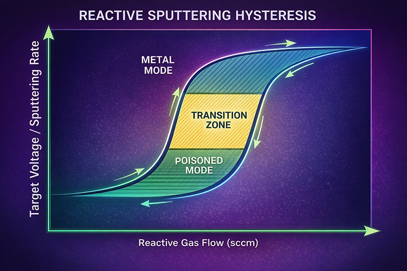
Here’s what happens. You introduce nitrogen or methane to react with your sputtered metal atoms and form the hard coating you need. But if the reactive gas flow is too high, the target surface itself begins to react—forming a compound layer that sputters much more slowly than the pure metal. Suddenly, your deposition rate plummets. The voltage and current behavior shifts. And if you’re in DC mode, you risk arc discharges that create macroparticles and defects in your coating.
The result: scrapped parts, rework, and process instability that eats into your margins.
How to take control:
1. Understand your hysteresis curve. Every target material and reactive gas combination has a characteristic relationship between gas flow and process parameters. The key is finding the “knee” where you transition from metal mode to poisoned mode—and operating just on the safe side.
2. Use mid-frequency AC or HIPIMS for reactive processes. If you’re still running DC for reactive nitride coatings, you’re fighting an uphill battle. Mid-frequency AC (typically 40 kHz) with twin targets allows each target to act as an anode during the opposite half-cycle, neutralizing charge buildup and virtually eliminating arcs. More advanced systems use HIPIMS (High Power Impulse Magnetron Sputtering), which delivers extremely high peak powers to create dense, defect-free coatings while maintaining stable reactive conditions.
3. Monitor optical emission. For tight control, consider adding an optical emission monitor (OEM) system that tracks the intensity of a metal spectral line. As poisoning begins, the metal signal drops. A closed-loop system can adjust reactive gas flow in real-time to maintain the target right at the desired operating point. This is the difference between a process that drifts and one that holds steady shift after shift.
4. Understand your target material’s reactivity. Different materials poison at different thresholds. Titanium and aluminum are highly reactive—they want to form nitrides and oxides. Vanadium, interestingly, shows different poisoning behavior and hysteresis width. If you’re running mixed materials (like AlCr targets), expect the reactivity to be dominated by the most reactive component.
The Integrated Approach: From Target to Process Parameters
Here’s where the math works in your favor. A 30% cost reduction doesn’t come from any single change—it’s the cumulative effect of multiple optimizations:
| Optimization Area | Typical Impact | Cumulative Effect |
|---|---|---|
| Rotary target design | +20-30% material utilization | Fewer target changes, less material waste |
| Indium-free bonding | +15-20% power capability | Faster deposition rates, shorter cycle times |
| Reactive process stabilization | -50% defect rate | Less scrap, higher yield |
| Closed-loop gas control | -10-15% gas consumption | Lower consumable costs |
Add these together, and 30% isn’t ambitious—it’s realistic.
At Stanford Advanced Materials (SAM), we’ve spent years refining this integrated approach. We don’t just supply targets; we provide application-matched solutions based on your specific coating requirements. For production-scale tool coaters, this means:
-
Rotary targets engineered for your cathode geometry, with optimized dimensions and verified bond quality (>95% bond rate)
-
Material selection guidance based on your target coating (AlCr for oxidation resistance, TiAl for toughness, or custom ratios)
-
Process parameter starting points derived from actual production runs, not theoretical models
-
Technical support that understands the difference between lab curiosity and production reality
Putting It Into Practice: A Production Example
Consider a typical tool coating line running AlTiN for end mills. The baseline operation:
-
Planar targets: 35% utilization, changed weekly
-
DC reactive sputtering: occasional arcing, 8% scrap rate
-
Manual gas control: process drifts across the shift, requiring operator intervention
After moving to optimized rotary targets with indium-free bonding, mid-frequency AC power, and closed-loop OEM control:
-
Target utilization: 72% (changed every 3 weeks)
-
Reactive process: stable, <2% scrap
-
Gas consumption: reduced 12%
-
Net result: 34% reduction in cost per coated tool
The numbers speak for themselves.
The Bottom Line
In production coating, the difference between a good operation and a great one isn’t magic—it’s attention to the fundamentals. Rotary target optimization and reactive sputtering control are the two levers that offer the biggest return on engineering effort.
If you’re ready to run the numbers on your own operation, we’d welcome the conversation. Sometimes the path to 30% cost reduction is clearer than you think.
Ready to analyze your coating costs?
Send us an inquiry to discuss your specific application. We’ll review your current targets, process parameters, and pain points—and provide a customized cost analysis with actionable recommendations. No generic sales pitch, just engineering talk.


